
Portfolio
Research-based Projects
Soft Robotic Snake Robot
University of Massachusetts Amherst · 2024 – PresentSnakes move across many different surfaces — rock, grass, bark, carpet — using different gaits and the frictional properties of their belly scales. These scales create anisotropic friction, meaning they resist motion more in one direction than another, which helps the snake push forward. The goal of this project is to build a soft robotic snake that uses the same principle: bio-inspired vertebrae, ribs, scales, and McKibben pneumatic muscle actuators working together to generate locomotion through friction.
Version 2 — Scale Design, Friction Characterization & Locomotion Correlation
In the second paper of this project, we wanted to understand whether the frictional properties of our scales actually predict how fast the robot moves — and on which surfaces. To do this, we built a modular scale system that lets us swap scale angles quickly, then ran friction and locomotion tests across multiple surfaces.
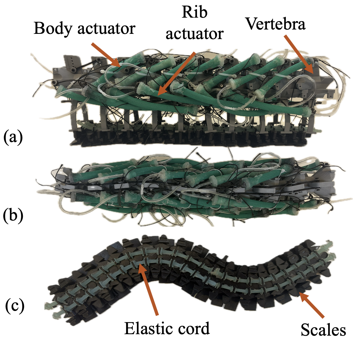
The snake robot with the modular scale system. (© 2026 IEEE)
Modular Scale Design
We designed a three-part scale structure that clips onto the robot's ribs:
- Primary unit — attaches directly to the ribs or to neighboring scale structures through a mechanical interlock. The connection mechanism was inspired by a train track toy.
- Secondary unit — snaps into the primary unit and defines the scale angle (θ). To change the angle, we just replace this piece.
- Tertiary unit — the actual scale, 0.5 mm thick, which slides into a groove on the secondary unit.
Elastomer cords run through the structures to keep things flexible. In total, the robot carries 22 scale structures. Rigid parts are 3D printed from PETG, and the cords are molded from Ecoflex 00-30.
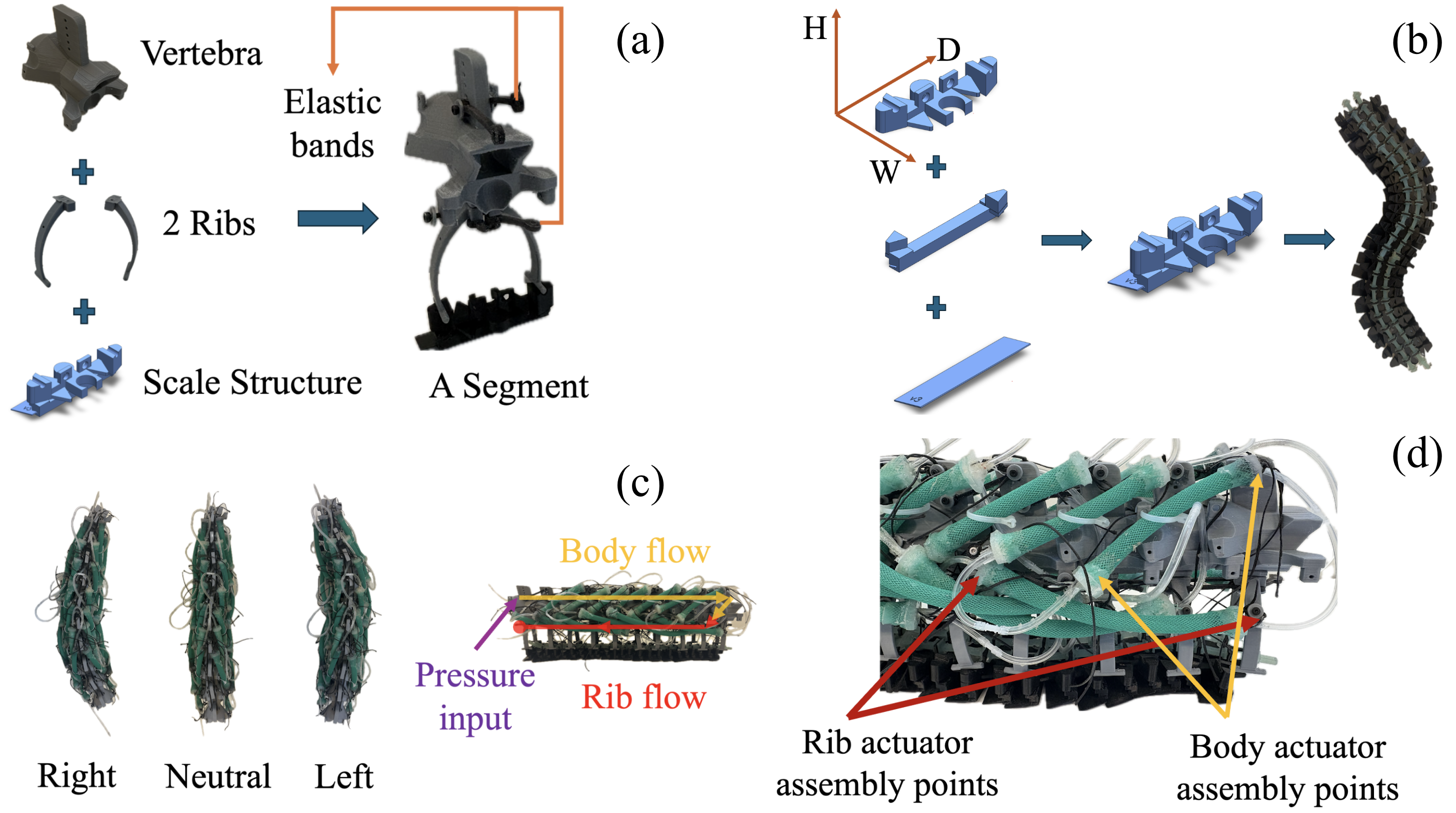
One robot segment showing the vertebra, ribs, and scale structure (a). Scale structure assembly with primary, secondary, and tertiary units, and how multiple structures interlock together (b). Left, neutral, and right actuation with air flow paths (c). Full assembly view (d). (© 2026 IEEE)
Friction Testing
We measured forward, backward, and lateral friction at four scale angles (15°, 25°, 35°, 45°) on four surfaces: grass, bark, smooth surface, and carpet. We used an Instron universal testing machine with a custom pulley setup, repeating each condition 5 times.
- Backward friction was consistently higher than forward friction on grass, bark, and carpet — especially at lower scale angles. This is the anisotropy that drives locomotion.
- On the smooth surface, friction was basically the same in all directions no matter the scale angle. Without surface texture, the scales can't generate useful anisotropy.
- Both the backward-to-forward (µb/f) and lateral-to-forward (µl/f) ratios dropped as we increased the scale angle.
- Lateral friction tended to be lower than forward friction, which probably explains the sideways drift we kept seeing in locomotion tests.
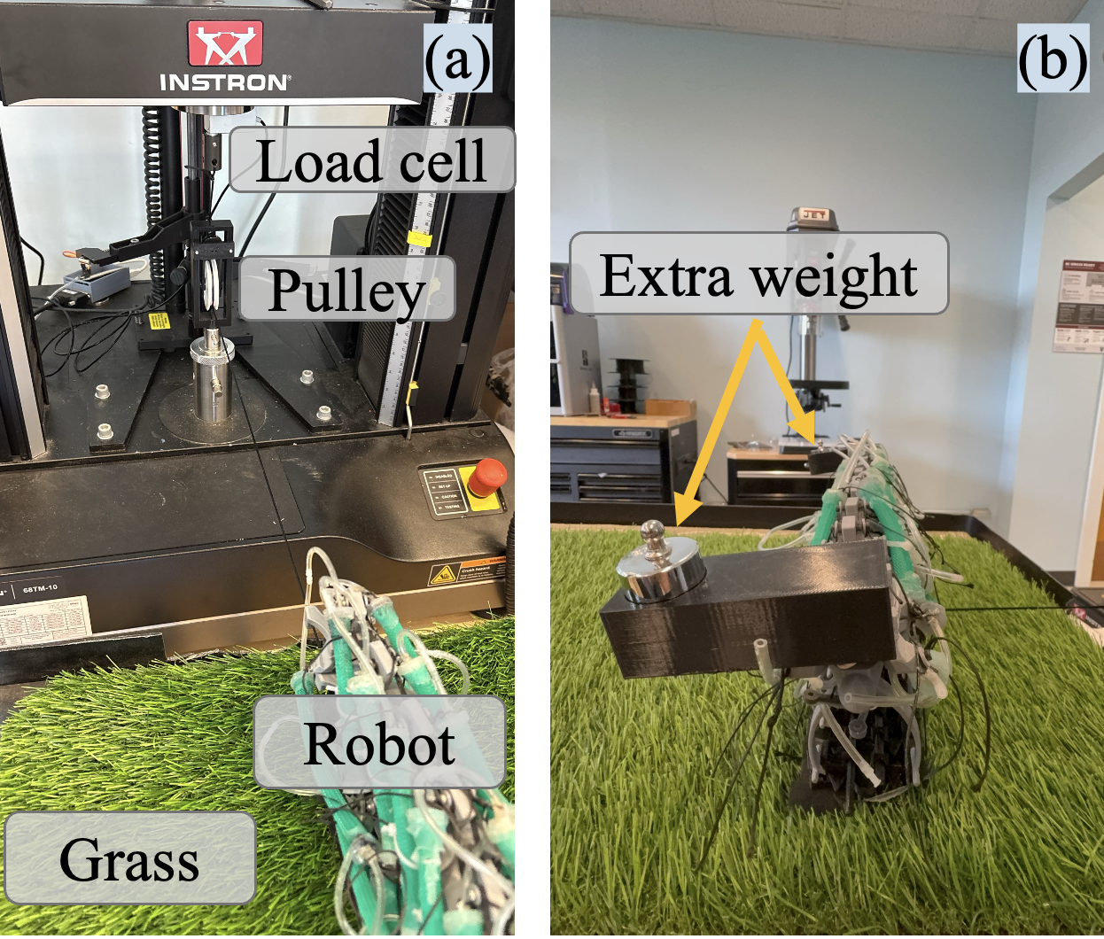
Experimental Test Setup. (© 2026 IEEE)
Locomotion Testing
We ran locomotion tests with a simple open-loop gait — inflate all actuators on one side for 3.5 seconds, deflate, then switch to the other side. Each trial ran for 5 minutes, except on bark where we cut it to 2.5 minutes because the robot kept moving off the surface. We tracked displacement in both the forward (x) and lateral (y) directions.
- Highest speed was on bark at a 25° scale angle.
- On grass at 15° and 25°, the robot moved mostly sideways rather than forward.
- On carpet, we only saw real locomotion at 15° and 25°. At higher angles, it barely moved.
- On the smooth surface, almost no displacement in any direction — which makes sense given the friction results.
Locomotion Video — Version 2
Key Findings
Friction ratios clearly changed with scale angle, but we couldn't find a clean relationship between those ratios and locomotion speed. Carpet had slightly higher ratios than grass, yet the robot moved faster on grass. Bark and carpet had similar ratios, but bark gave much higher speeds. So friction numbers alone don't tell the whole story — things like how the scales catch on surface features, stick-slip effects, and even the alignment of fibers on the surface seem to matter a lot, and those aren't captured by a standard friction test. One positive result is that the scale angles that worked best for us (15°–25°) are close to what's been measured on real snakes (20°–30°).
U. Sen, A. Mahegan, and G. Olson, "Characterization and Correlation of Robotic Snake Scale Friction and Locomotion Speed," in 9th IEEE-RAS International Conference on Soft Robotics (RoboSoft), 2026. arXiv:2603.03735
Version 1 — Robot Design & Initial Locomotion
In the first paper, we designed and 3D printed a bio-inspired snake robot and demonstrated that anisotropic friction leads to locomotion in soft robotic snakes. The robot consists of vertebrae, ribs, and scales inspired by biological snakes, with McKibben pneumatic muscle actuators mimicking the iliocostalis and semispinalis muscles.
- Designed snake-inspired vertebrae, ribs, and scale components in SolidWorks and fabricated them using FDM 3D printing.
- Fabricated initial scales by molding PETG-printed scales with a polyurethane mold base, mimicking dorsal scales of biological snakes.
- Fabricated 2+ generations of McKibben actuators to improve pneumatic actuation quality.
- Mimicked the lateral undulation gait of snakes to generate forward locomotion.
- Demonstrated both vertical and lateral bending capabilities of the robot.
- Performed material testing to analyze bonding between elastomers and thermoplastics using a universal testing machine.
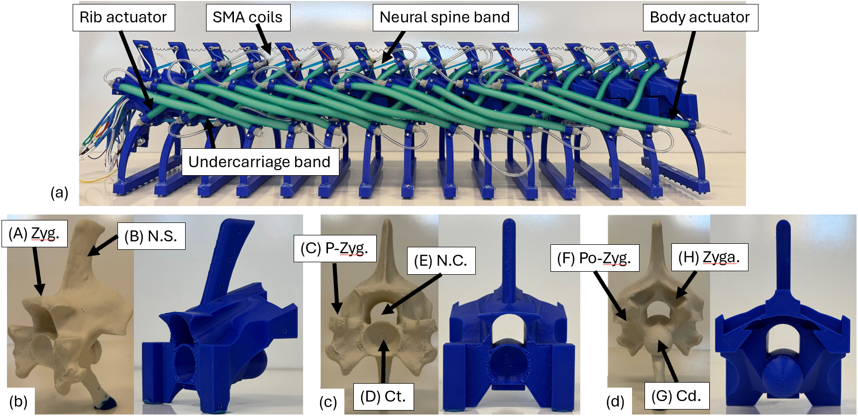
The robot and snake-inspired vertebral design (from: doi:10.1007/978-3-032-07448-5_20)
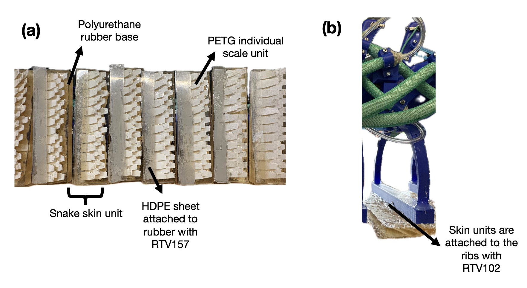
Scale details and their attachment to the robot (from: doi:10.1007/978-3-032-07448-5_20)
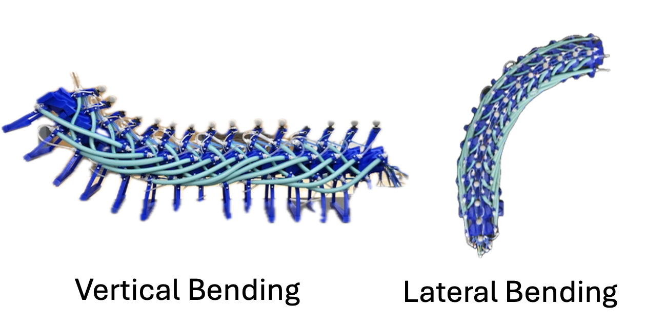
Bending capabilities of the robot (from: doi:10.1007/978-3-032-07448-5_20)
Locomotion Video — Version 1
Y. Nandwana, U. Sen, and G. Olson, "A Highly Articulated Backbone for Soft Snake Robots," in Biomimetic and Biohybrid Systems (Living Machines), Sheffield, UK, 2025. doi:10.1007/978-3-032-07448-5_20
Wrist-Worn Haptic Device
Kadir Has University · 2022 – 2023For my senior thesis, I designed a wrist-worn haptic device that moves tactile feedback from the fingertip to the wrist. The idea is to free up the fingers for VR/AR interaction while still giving the user useful touch feedback. The core of the device is a custom voice-coil actuator — a magnet and coil setup where you can tune the force output by changing parameters like coil height, wire thickness, and magnet strength.
- Built a custom voice-coil actuator with neodymium magnets and optimized coil geometry.
- Went through 10+ 3D-printed case prototypes to get the fit, comfort, and force transmission right.
- Wrote embedded firmware for real-time actuation with tunable intensity via duty cycle and frequency control.
- Built a Unity3D interface for controlling and testing the device.
- Ran user studies on stiffness discrimination to validate that the device can reliably convey different tactile cues.
This work led to two publications: one at IEEE World Haptics 2023 and one in IEEE Robotics and Automation Letters (RA-L) 2024.
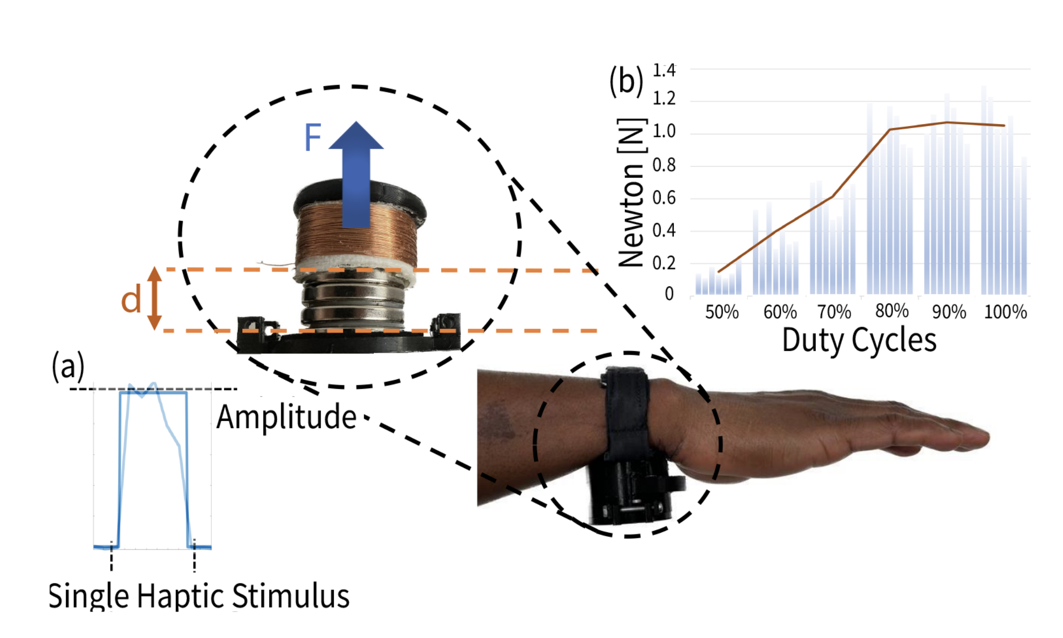
Demonstrates the actuator’s operation and force response under varying duty cycles. (From: DOI: 10.1109/LRA.2024.3360815, (© 2024 IEEE))
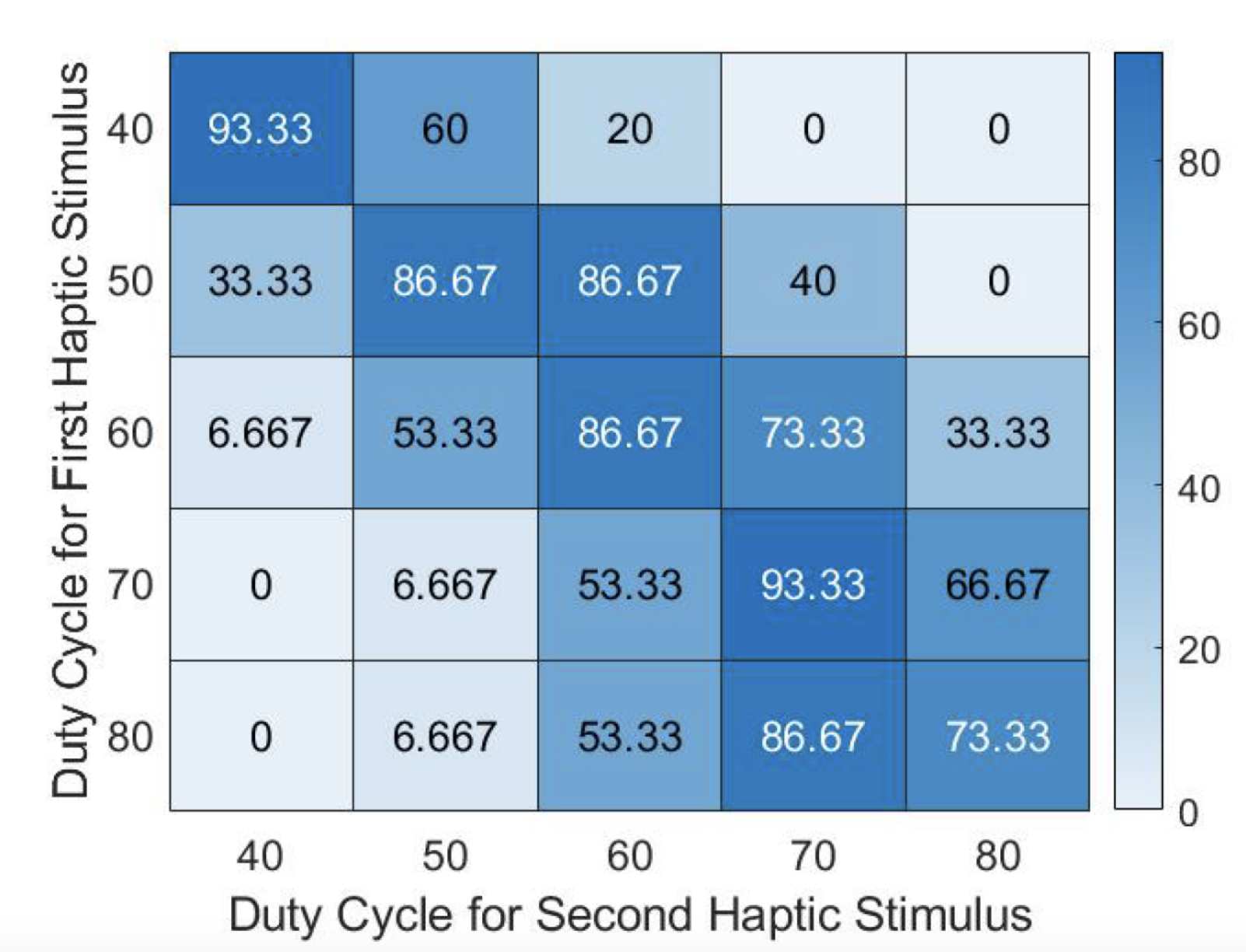
Shows user discrimination accuracy across actuator duty cycles. (From: DOI: 10.1109/LRA.2024.3360815, (© 2024 IEEE))
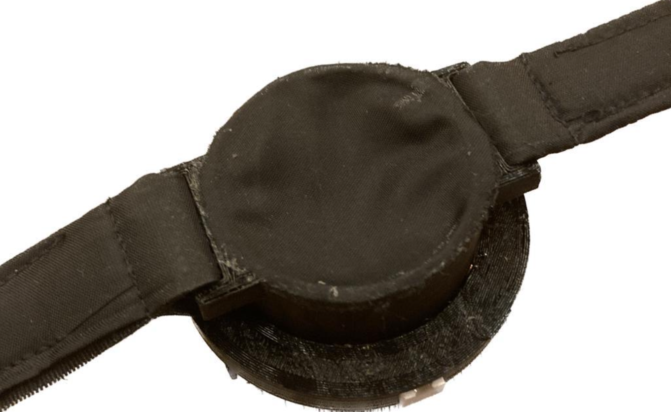
Soft satin fabric ensures comfortable and stable contact while maintaining consistent force transmission.
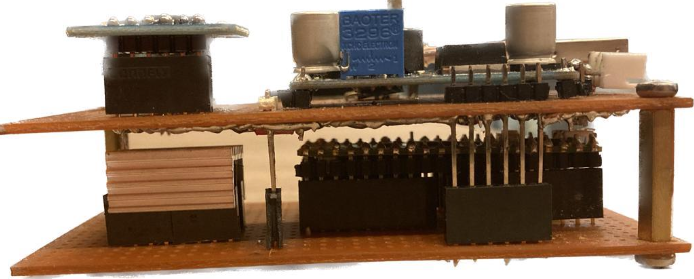
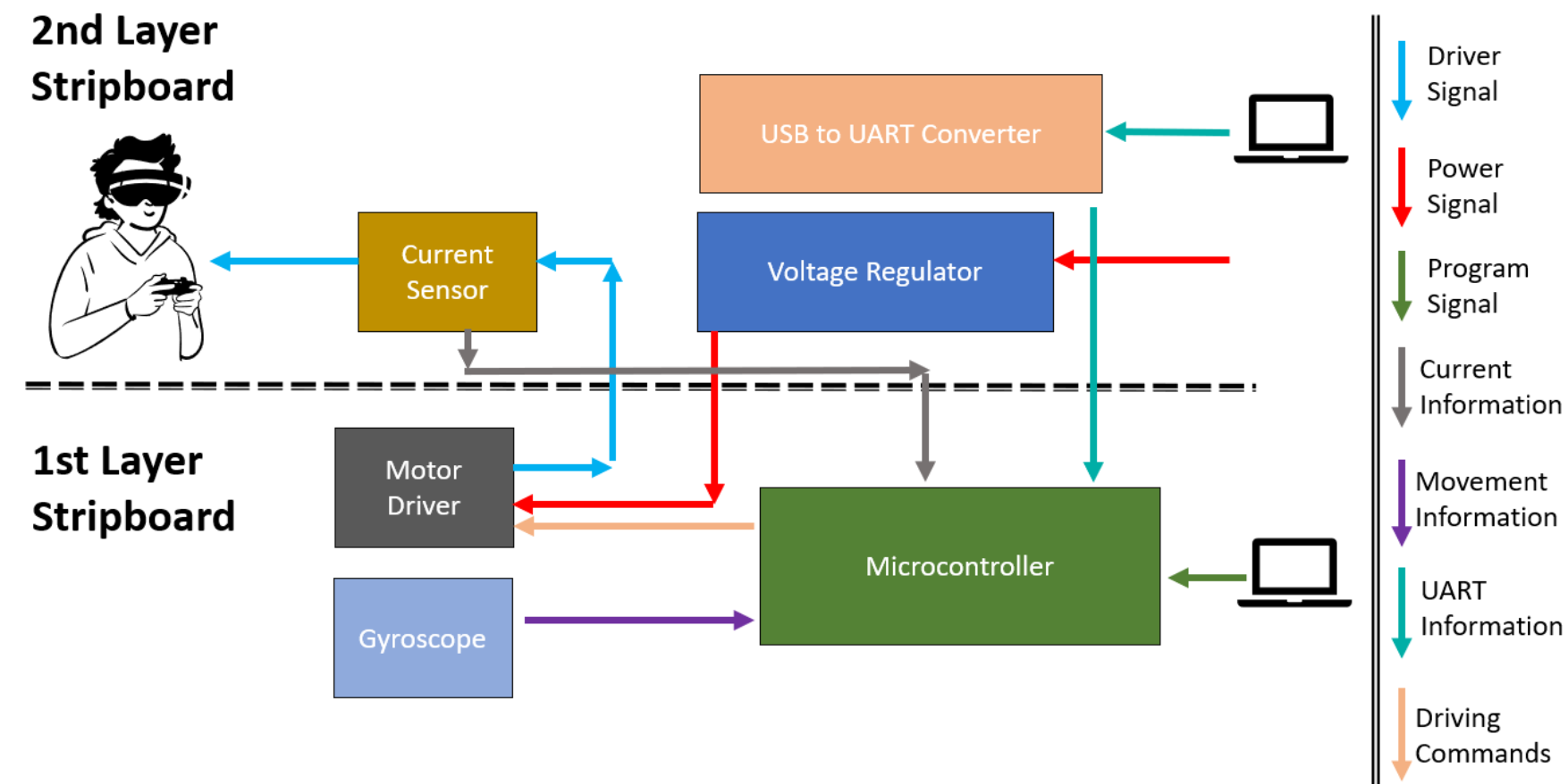
Compact two-layer board that integrates control, sensing, and actuation electronics.
Haptic Game Development
Kadir Has University · 2024We built a smartphone game in Unity3D as a way to run tactile perception experiments without boring the participants. Instead of a traditional psychophysical test, users play an endless runner — navigating a ball through a path with walls — while the phone delivers different types of haptic feedback. This lets us collect data on how people respond to touch cues in a setting that's actually engaging.
- Developed for iOS with optimized haptic rendering.
- The player controls a ball moving through a path with walls, using on-screen arrow buttons.
- Implemented three haptic feedback modes using Interhaptics Composer: feedback on collision only, feedback that scales with how far into the wall the ball goes, and predictive feedback that kicks in before the ball even hits the wall.
- Paths are procedurally generated with varying wall angles, so gameplay stays unpredictable across sessions.
- The game logs all user actions in real time — collisions, inputs, transitions between haptic zones — for analysis.
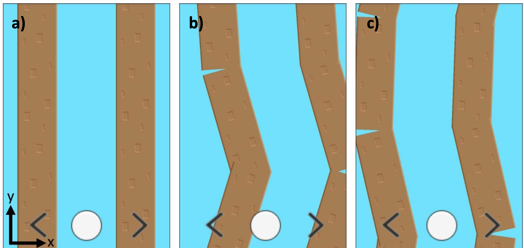
Screenshots of the mobile game during a playthrough. The player (a white ball) appears at the bottom of the screen, navigating a path bordered by brown walls. Movement along the x-axis is controlled via on-screen arrow buttons, while progression along the y-axis occurs automatically. The images show: (a) the start of the game, (b) a collision with the left wall, and (c) recovery back to the center path.
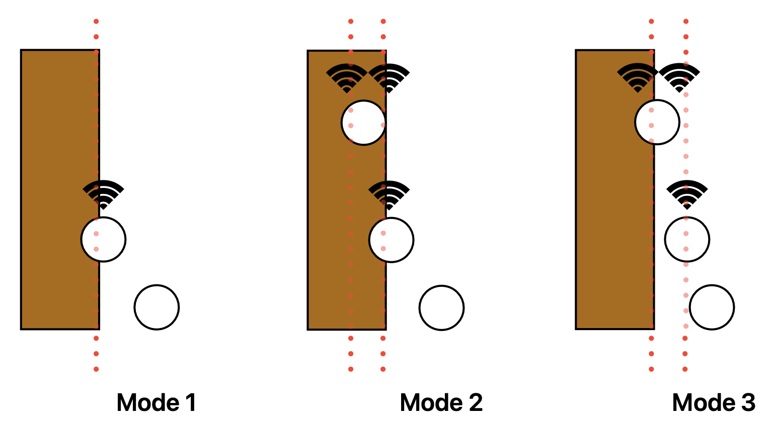
Representation of three haptic feedback modes: (i) fixed feedback triggered only on collision, (ii) variable feedback intensity based on the ball’s penetration depth into the wall, and (iii) predictive haptic guidance that increases in strength as the ball approaches and contacts the wall.
Course & Competition Projects
Pod Design for Hyperloop Competition
National Hyperloop Competition · 2022This project was developed for a national (Türkiye) Hyperloop competition, where our team received the Best Technical Design Report Award. I worked as part of the Navigation and Electronics Team, and focused on the design and testing of the systems that guided and monitored the pod’s movement inside the tunnel. My main goal was to build a reliable and accurate navigation setup that could work at high speeds using multiple sensors and Arduino-based control systems.
- Designed a reflector-based navigation system using laser sensors and Arduino Due to detect tunnel reflectors at speeds up to 26 m/s.
- Wrote and tested Arduino scripts to calculate velocity and displacement from reflector detection intervals.
- Contributed to design of a redundant sensor layout with five laser modules to reduce error through majority voting logic.
- Developed a backup tachometer system using TCRT5000 IR sensors to track wheel rotation when laser sensors failed.
- Integrated MPU6050 IMU and height IR sensors to measure acceleration, tilt, and levitation height of the pod.
- Matched sampling frequencies and designed an optimized signal flow between sensors and the main computer to ensure realiable data transmission.
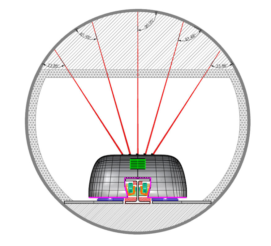
Placement of laser sensors used for pod navigation and reflector detection.
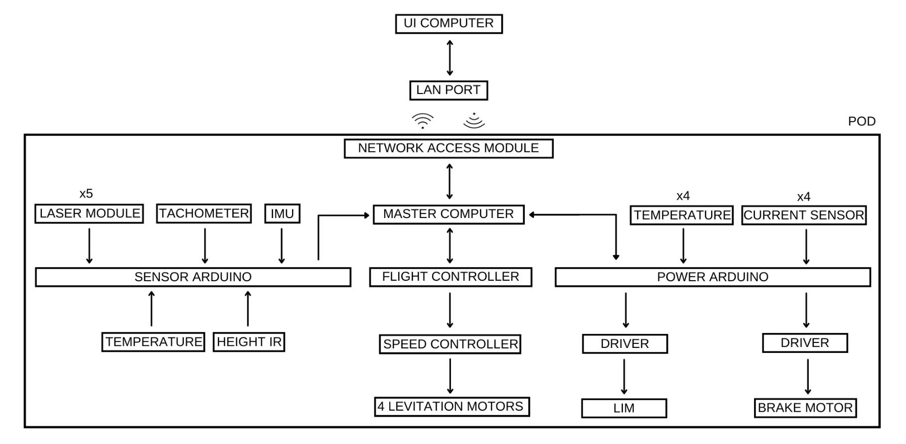
Overall system architecture illustrating the integration of sensors with the microcontroller and master computer for pod navigation.
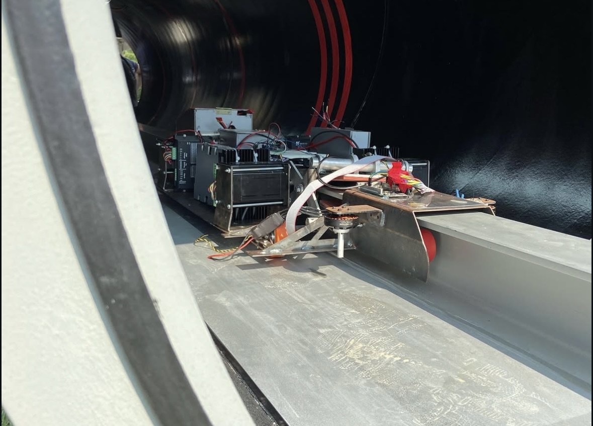
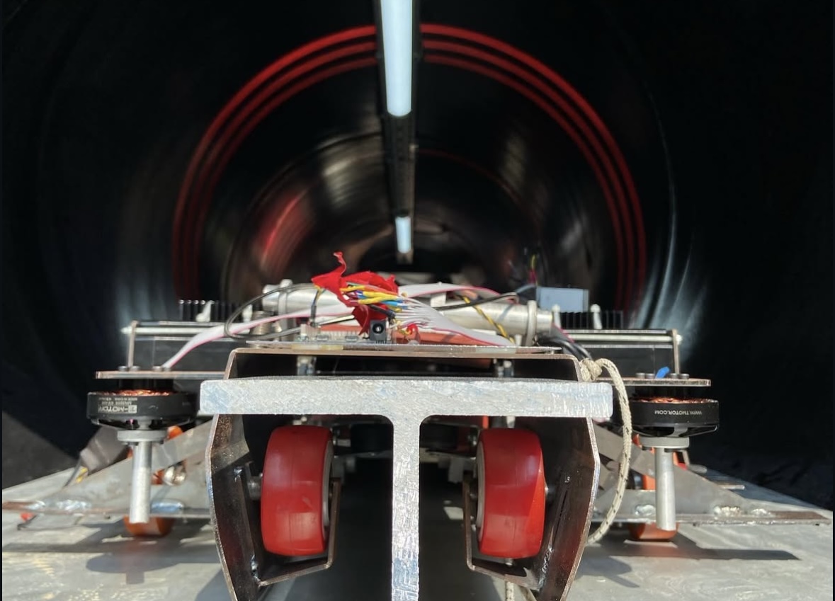
Manufactured pod placed on the competition track.
Robotic Teleoperation System
Class Project · Low-cost dual-arm teleoperation platform using ROS and Arduino · 2023For this class project, I built a low-cost teleoperation system using two 3D-printed robotic arms — one as the controller and one as the teleoperated arm. The idea is simple: I move the controller arm by hand, potentiometers read the joint angles, and those angles get sent over ROS to the other arm, which mirrors the motion. It works well enough for basic pick-and-place tasks, with about 0.3–0.5 seconds of delay based on frame-by-frame video analysis.
- Designed and 3D printed both arms from PLA, using SG90 servos for actuation.
- Used potentiometers at each joint for position sensing — cheap but accurate enough for this setup.
- Set up a ROS publisher-subscriber system for wireless communication between the two arms.
- Tested with pick-and-place tasks (only light objects — SG90 servos don't have much torque).
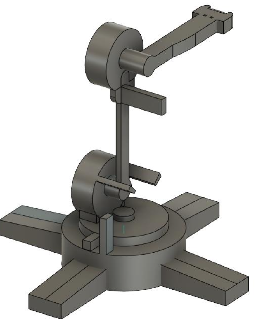
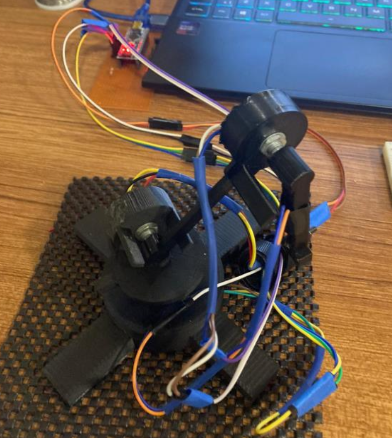
Controller Arm: 3D-printed design and assembly of the master arm used to control the teleoperated manipulator. Potentiometers are integrated into each joint for angular position sensing and transmission via ROS interface
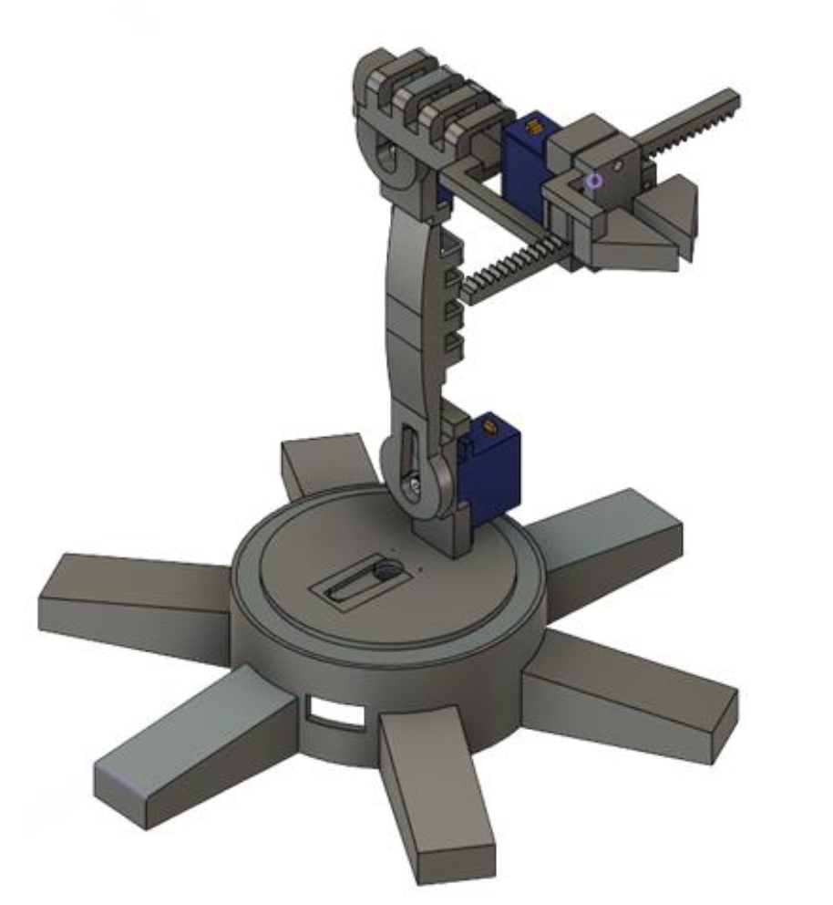
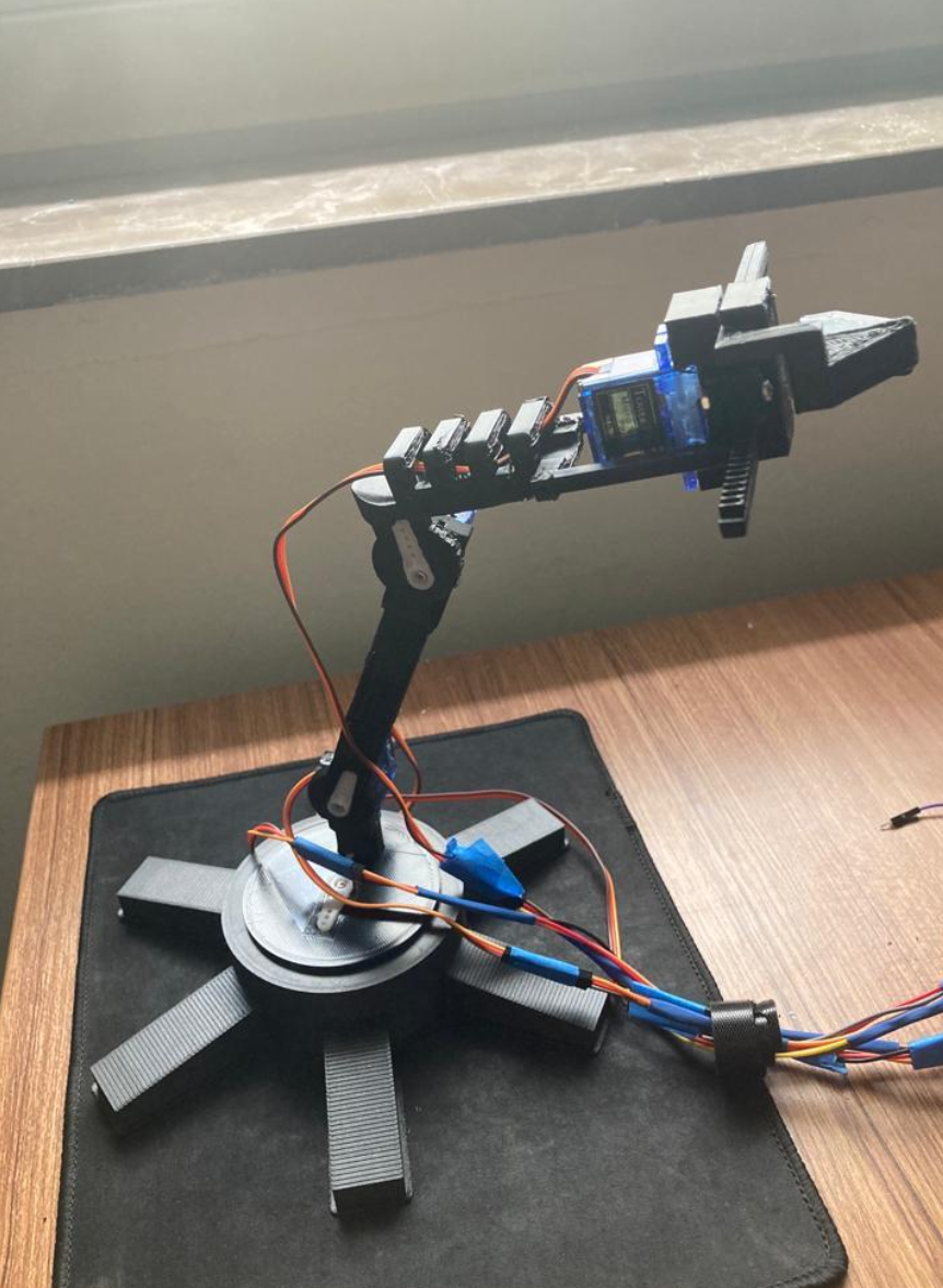
Teleoperated Arm: Replicated arm executing the controller’s movements in real time.

System Architecture: Overview of the teleoperation framework showing the data flow between the controller and teleoperated arms through the ROS publisher–subscriber system. Each joint angle is obtained via potentiometers and transmitted to replicate movement on the teleoperated side. The setup enables low-cost, real-time wireless control.
Demonstration Video